MELSEC Tutorial 07 – Ladder Logic Programming: Data Transfer
In ladder logic programming, data transfer instructions are crucial for moving data between devices, memory locations, or registers in a MELSEC PLC system. These instructions are foundational for creating dynamic and efficient control systems that require seamless communication and data management. This tutorial will guide you through the concepts, implementation, and best practices for using data transfer instructions in GX Works3.
-
MELSEC Tutorial 01 – PLC System Configuration
MELSEC Tutorial 01 – System Configuration, Installation, and Wiring Setting up a MELSEC PLC system is the first step in…
-
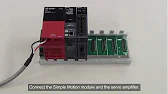
MELSEC Tutorial 02 – PLC Module Configuration Diagram

MELSEC Tutorial 02 – Module Configuration Diagram Creating a module configuration diagram is a critical step in setting up a…
-
MELSEC Tutorial 03 – Ladder Program
MELSEC Tutorial 03 – Ladder Program In industrial automation, programming controls the behavior of devices and systems. MELSEC Ladder Programming…
-
MELSEC Tutorial 04 – Create a Ladder Program
MELSEC Tutorial 04 – Create a Ladder Program Industrial automation relies heavily on programming to implement control logic for machines…
-
MELSEC Tutorial 05 – Ladder Sequence Instructions
MELSEC Tutorial 05 – Ladder Logic Programming Sequence Instructions Ladder Logic Programming is a vital skill for developing control systems…
-
MELSEC Tutorial 06 – Ladders Timers and Counters
MELSEC Tutorial 06 – Ladder Logic Programming: Timer and Counter MELSEC Timers and counters are fundamental tools in ladder logic…
-
MELSEC Tutorial 07 – Ladder Logic Programming Data Transfer
MELSEC Tutorial 07 – Ladder Logic Programming: Data Transfer In ladder logic programming, data transfer instructions are crucial for moving…
-
MELSEC Tutorial 08 – Ladder Comparison Operations
MELSEC Tutorial 08 – Ladder Logic Programming: Comparison Operation In industrial automation, MELSEC comparison operations play a vital role in…
-
MELSEC Tutorial 09 – Ladder Arithmetic Operations
MELSEC Tutorial 09 – Ladder Logic Programming: Arithmetic Operations MELSEC arithmetic operations form the backbone of ladder logic programming, enabling…
-
MELSEC Tutorial 10 – Ladder Input Instructions
MELSEC Tutorial 10 – Ladder Logic Programming: Input Instructions MELSEC Ladder logic programming depends on input instructions to define how…
-
MELSEC Tutorial 11 – Creating ladder logic comments
MELSEC ladder logic Creating Comments, Statements, and Notes When programming with ladder logic, clarity is essential to ensure the program…
-
MELSEC Tutorial 12 – Writing to PLC
MELSEC Tutorial 12 – Writing to PLC In this tutorial, we’ll explore how to write programs to a PLC using…
-
MELSEC Tutorial 13 – Debugging and Maintenance
MELSEC Tutorial 13 – Debugging and Maintenance Efficient debugging and maintenance are critical aspects of working with MELSEC PLC systems,…
Understanding Data Transfer in Ladder Logic
Data transfer instructions allow you to:
- Move data between two locations, such as registers (D, W) or counters.
- Exchange data with external devices connected via networks.
- Prepare variables for further processing in mathematical or logical operations.
Key instructions in MELSEC ladder logic include:
- MOV (Move): Transfers a single value from one location to another.
- BMOV (Block Move): Transfers a block of consecutive data.
- ZRST (Zero Reset): Resets a block of registers to zero.
Step 1: Setting Up Data Registers
Before transferring data, identify the source and destination registers:
- Open GX Works3 and access the Device/Label Editor.
- Define the source register (e.g.,
D0) and destination register (e.g.,D10). - Specify initial values for testing, if required.
Step 2: Implementing the MOV Instruction
Example: Simple Data Transfer
Scenario: Transfer the value 123 from data register D0 to register D10.
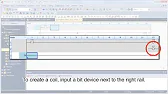
- Insert the MOV instruction in the ladder logic editor.
- Specify
D0as the source andD10as the destination.
Ladder Logic Code:
Condition --] [-- MOV D0 D10 --( )--
When the condition is true, the value in D0 will transfer to D10.
Step 3: Using BMOV for Block Data Transfer
Scenario: Transfer five consecutive values starting at D20 to registers starting at D50.
- Use the BMOV instruction.
- Specify
D20as the starting source address andD50as the starting destination address. - Set the number of words to transfer as
K5.
Ladder Logic Code:
Condition --] [-- BMOV D20 D50 K5 --( )--
This will move values from D20-D24 to D50-D54.
Step 4: Resetting Data with ZRST
Scenario: Reset a block of registers starting from D30 for 10 words.
- Insert the ZRST instruction.
- Specify
D30as the starting address andK10as the number of registers to reset.
Ladder Logic Code:
Condition --] [-- ZRST D30 K10 --( )--
This resets D30-D39 to zero when the condition is true.
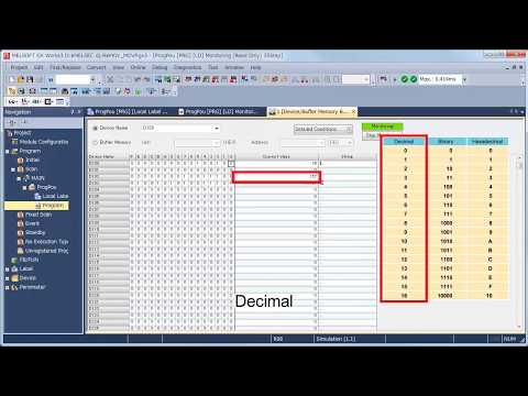
Step 5: Monitoring Data Transfers
Using the Device Monitor:
- Open the Device/Monitor tool in GX Works3.
- Add the registers involved in data transfer (
D0,D10, etc.) to the watch list. - Observe the values in real time to verify that data moves correctly.
Advanced Tip: Conditional Data Transfers
For more complex scenarios, use comparison instructions to determine whether data should transfer.
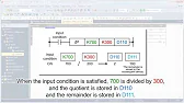
Scenario: Transfer data from D40 to D50 only if the value in D40 exceeds 100.
- Insert a comparison instruction (
>) to check the condition. - Trigger the MOV instruction based on the comparison result.
Ladder Logic Code:
D40 > K100 --] [-- MOV D40 D50 --( )--
Conclusion
Data transfer is a core functionality in ladder logic programming, enabling smooth operation and communication in industrial automation systems. By mastering the MOV, BMOV, and ZRST instructions, you can handle various data management tasks efficiently in your MELSEC PLC projects. Understanding these concepts will empower you to create more responsive and adaptable control systems.
