PLC Ladder Diagram Basics
INTRO
PLC ladder diagram basics are essential for understanding how industrial control systems are structured. Before writing PLC programs, engineers must understand how diagrams represent electrical systems.
In this guide, you will learn how ladder diagrams are organized and how wiring standards improve safety and readability.
🧠 PLC LADDER DIAGRAM BASICS STRUCTURE
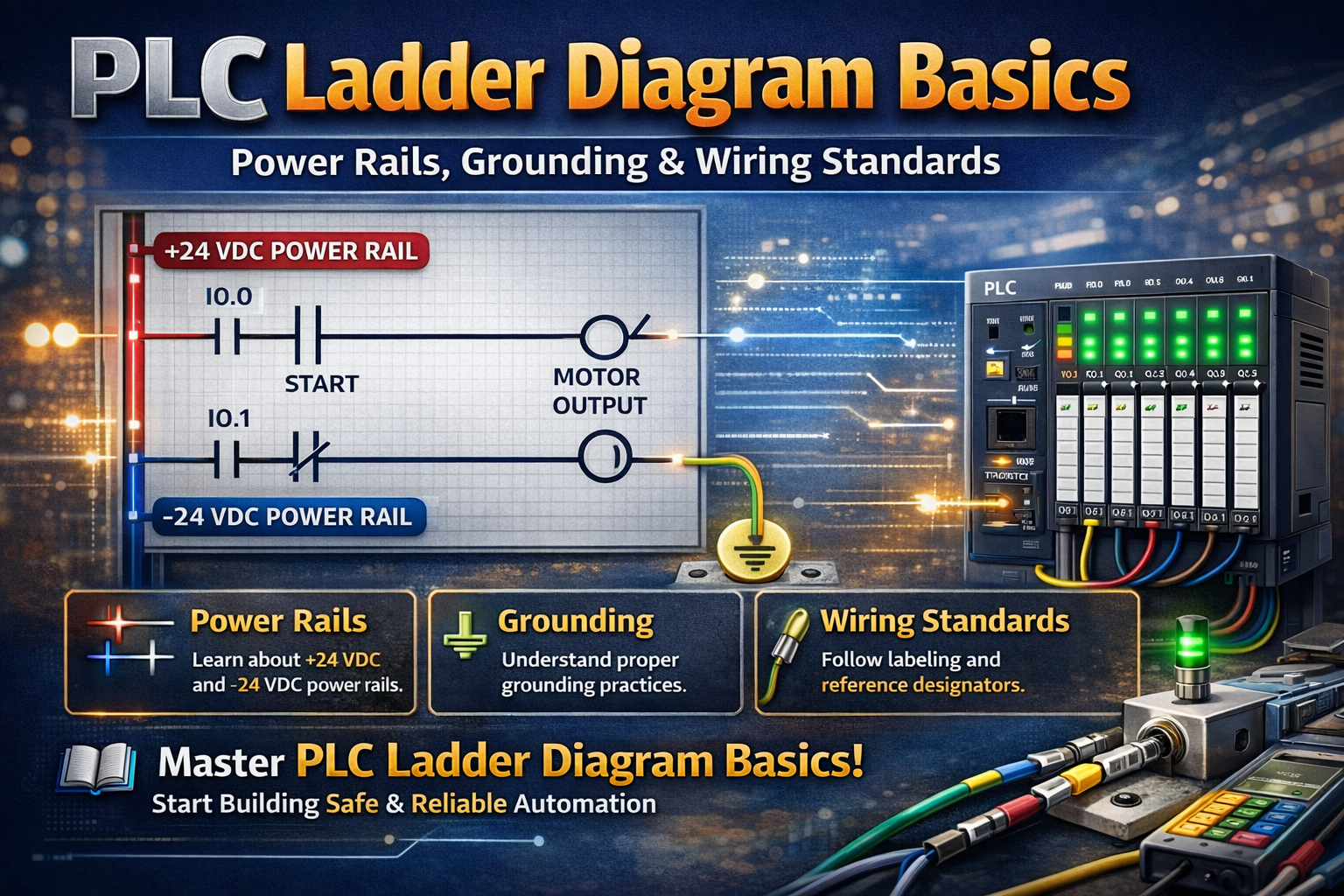
Ladder diagrams follow a standardized structure used in industrial control systems. They include vertical power rails and horizontal connections that define the control logic.
For example, the two rails represent voltage potential, while the rungs connect control elements. As a result, engineers can quickly understand system behavior.
⚙️ POWER RAILS AND GROUNDING
Power rails define the electrical framework of a ladder diagram. One rail typically carries the supply voltage, while the other represents the return path.
In addition, proper grounding of the control system is critical. Grounding the secondary side of a transformer improves safety and helps prevent electrical hazards.
🔧 WIRING STANDARDS AND COLOR CODING
Wiring standards ensure consistency and safety in industrial systems. Engineers use wire markers to label connections and simplify troubleshooting.
For example, common color codes include:
- Black and red for control voltage
- White for neutral
- Green for grounding
Because of this, technicians can identify circuits quickly and avoid mistakes.
🔄 MTW VS. THHN WIRING
Different types of wires are used depending on the environment. MTW (Machine Tool Wire) is suitable for industrial environments, especially where oil or mechanical stress is present.
On the other hand, THHN wire is commonly used for general electrical installations. Therefore, selecting the correct wire type improves durability and safety.
🏷️ REFERENCE DESIGNATORS
Reference designators are used to label components in a ladder diagram. These labels make diagrams easier to read and maintain.
For example:
- CR for control relays
- LS for limit switches
As a result, engineers can track components and modify systems more efficiently.
🌍 WHY THESE BASICS ARE IMPORTANT
Understanding PLC ladder diagram basics is important because it forms the foundation of all automation systems. Without proper structure and labeling, systems become difficult to maintain.
Therefore, learning these principles helps engineers build safe and reliable control systems.
🏭 REAL APPLICATIONS
These concepts are used in many industrial systems. For example:
- Control panels
- Machine automation
- Manufacturing systems
- Process industries
In addition, they help standardize system design across different industries.
🔗 RELATED TOPICS
✅ CONCLUSION
PLC ladder diagram basics provide the structure needed to design and understand industrial control systems. By learning power rails, grounding, and wiring standards, you can build more reliable automation solutions.
Over time, this knowledge allows you to work more efficiently in complex industrial environments.
✅ Social platforms
Subscribe in out Youtube channel for more videos:
- PLC Programming YouTube Channel: https://nuel.ink/9YxAHA
- Mitsubishi Training YouTube Channel: https://nuel.ink/2eFPGR
Follow us on Social Media:
- LinkedIn: https://nuel.ink/e6ZxM2
- Facebook Page: https://nuel.ink/xh5xhN
- Facebook Group: https://nuel.ink/aYciCv
- Instagram: https://nuel.ink/JSAjeD
- Twitter: https://nuel.ink/QGXW2L
- E-mail: info@plc-courses.com