PLC Ladder Diagram Fundamentals
INTRO
PLC ladder diagram fundamentals are essential for understanding industrial machine control systems. These diagrams provide a structured way to design and analyze electrical control logic.
In this guide, you will learn how ladder diagrams are built and how common components are used in real automation systems.
🧠 PLC Ladder Diagram Fundamentals Structure
Ladder diagrams follow a clear structure that represents electrical control systems. They include vertical rails and horizontal rungs that define the logic flow.
For example, each rung connects inputs and outputs using logical relationships. As a result, engineers can easily read and understand the control system.
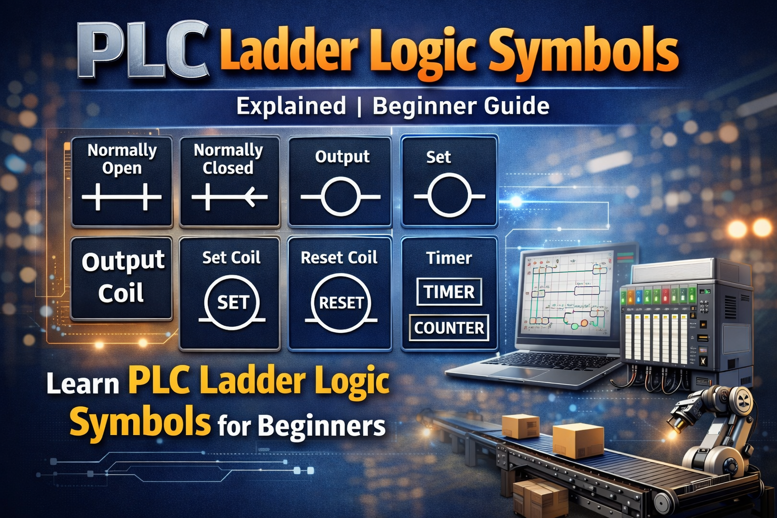
⚙️ KEY COMPONENTS AND SYMBOLS
PLC ladder diagram fundamentals include several important components:
- Contacts and switches
- Loads such as relays and outputs
- Branches and connections
- Time delay relays
Each symbol represents a real electrical component used in machine control systems.
🔧 TRANSFORMERS AND CONTROL VOLTAGE
Control systems often use transformers to reduce voltage to safe levels. Typically, engineers use 120V AC or lower for control circuits.
In addition, dual-primary transformers allow flexible operation with different input voltages such as 240V or 480V. Because of this, systems can adapt to various industrial environments.
⚡ CIRCUIT PROTECTION
Circuit protection is a key part of ladder diagram design. Engineers use slow-blow fuses to protect transformers and control circuits from damage.
Therefore, proper protection ensures safe and reliable system operation.
🌍 WHY LADDER DIAGRAMS ARE IMPORTANT
Ladder diagrams are widely used because they simplify complex control systems. They provide a clear way to design, troubleshoot, and maintain automation systems.
As a result, engineers across different industries rely on these diagrams for machine control.
🏭 REAL APPLICATIONS
Ladder diagrams are used in many industrial applications. For example:
- Machine control systems
- Manufacturing automation
- Electrical control panels
- Process industries
In addition, they help standardize system design and improve reliability.
🔗 RELATED TOPICS
✅ CONCLUSION
PLC ladder diagram fundamentals provide the foundation for understanding industrial automation systems. By learning symbols, structure, and components, you can design and analyze control systems effectively.
Over time, this knowledge allows you to work with complex automation environments.
✅ Social platforms
Subscribe in out Youtube channel for more videos:
- PLC Programming YouTube Channel: https://nuel.ink/9YxAHA
- Mitsubishi Training YouTube Channel: https://nuel.ink/2eFPGR
Follow us on Social Media:
- LinkedIn: https://nuel.ink/e6ZxM2
- Facebook Page: https://nuel.ink/xh5xhN
- Facebook Group: https://nuel.ink/aYciCv
- Instagram: https://nuel.ink/JSAjeD
- Twitter: https://nuel.ink/QGXW2L
- E-mail: info@plc-courses.com